Setting Up The Drill: The drill is placed in the desired location for the hole, leveled, and the derrick raised. One end of the sand line is attached to the vacuum sand pump; the other end is placed over the sand line sheave in the derrick and attached to the sandline drum. The drill line is placed over the crown sheave of the derrick, laced through the walking beam, and attached to the mainline drum, the cable socket being on the other end of the line.
For most placer operations, a string of tools usually consists of a rope socket, a stem, and a hit. When assembling a string of tools, lay the stem on the ground at the front of the drill; screw on the rope socket with the attached cable; then screw the bit on the lower end of the stem. A light wire brush and gasoline is recommended to clean the threads before assembling. A few drops of light oil are desirable on the threads.
Great care must be exercised in assembling a string of tools to see that the joints are tight. Screw the tool joints up by hand, then apply tool wrenches and set the joint up firmly by means of the chain wrench bar. Remember, most fishing jobs are due to improper setting of joints.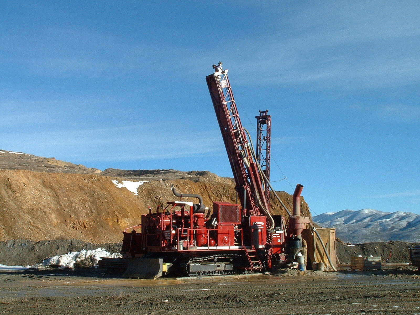
Many drillers use a stone in polishing the shoulder portion of the box and pin, before assembling. After a joint has been set up perfectly solid, a mark is sometimes made with a sharp cold chisel, half on the pin collar and half on the box. Each successive time this joint is screwed up, the mark on the box should go a little farther past the mark on the pin collar. By this method one can check and see that the joint is set up firmly. If, at the next fitting the joint does not go far enough, it is indicative that there is dirt on the face of the joint — or in the threads, which dirt must be removed.
After the stem and bit have been assembled, the tools are hoisted, the operator being careful not to kink the cable where it enters the socket. Check the frame to see that the tools hang directly above the centerline of the drill and approximately 24 inches out from the front of the drill. You are now ready to start the hole.
Starting a Hole: At the site marked for drilling, a hole is dug approximately 16 inches deep. The gravel removed is examined to see whether it contains gold. A drive shoe is placed on one end of a length of drive pipe and a drive head on the other.
After carefully measuring the length of the pipe and shoe they are placed in the hole in a vertical position with the drive shoe on the bottom. Dirt is packed around the pipe to hold it in position. Where long lengths of casing are used, a well is usually dug directly in front of the drill. This is very difficult to do in wet ground.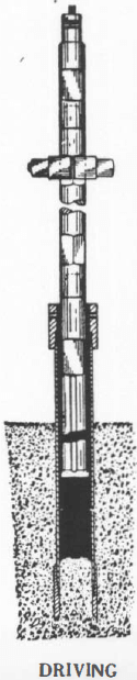
DRIVING THE PIPE
THE TOOLS are lowered, allowing the bit to enter the casing, the drive clamps are clamped on the square on the hit. It is important to see that the drive clamp bolts are kept tight. Loose nuts mean certain breaking of bolts.
The engine of the drill is started and operated at slow speed.
The drive clamps are lowered to within three inches of the drive head, the spudding lever is moved to the “On” position, and the casing gently tapped into the ground. The impact blow and feed are adjusted by gently raising the brake lever.
If the topsoil is valueless, the pipe is driven to gravel. When the drive head reaches a point a few inches from the ground, it is removed and another length of pipe is carefully measured and coupled to the first length, care being taken to couple the pipe so that they butt in the center of the coupling. The drive head is then placed on the top of the next section of pipe and the operation resumed, core in the meantime is being removed as the pipe is driven deeper.
Whenever pipe is added, the threads are carefully cleaned and then greased with graphite and linseed oil and securely tightened by means of chain tongs. It is very important to grease the pipe and not the couplings. The portion of the thread one-quarter inch back from the end of the pipe is the part usually lubricated.
As soon as the hole has reached a depth sufficient for the bit and stem to enter the casing, the drive clamps are placed on the top square of the stem. After driving pipe to the desired depth, the drive clamps are removed.
Records are made of the depth of the drive pipe and also the core. By starting at the hit and measuring back along the stem, the total length of pipe is marked with chalk or a piece of string on the line. The stem is lowered into the pipe and the distance between chalk mark and the top of the pipe represents the core remaining in the hole.
DRILLING OPERATIONS
DRILLING PROCEDURE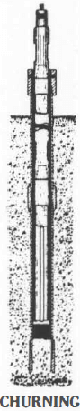
DRILLING proceeds in the following manner: The driller measures and reports the length of core to the panner. This, and the depth of casing in the ground, are recorded in the log book.
Water is poured into the casing, the spudding lever thrown in the “On” position, and the core chopped up.
Some operators place a spoonful of lye in the drill hole when churning. Lye cuts any grease from the fine gold and prevents it floating away. There are times when there is a certain amount of vegetable oil in the ground or grease from pipe threads or wire line.
In placer testing it is always customary to try to drive the casing ahead of drilling. Three or four inches of core are always left in the casing to form a plug. This is contrasted with other types of drilling where the churning is done below the casing.
When large boulders are encountered, it is necessary to drill below the drive shoe; then the operator should check to see that the water level in the pipe is at least as high as the water plane in the ground, to prevent any values being carried into the casing.
When drilling through boulders greater speed can be obtained by using an ordinary rock bit or a four-wing type bit, than with a placer bit.
PUMPING OUT THE CORE
THE TOOLS are hoisted out of the pipe and held out of line of the drill casing by means of the tool guide. While the tools are being hoisted, a bucket-of water is usually poured on the rope and stem to wash off any values that might be clinging to the tools. The sand pump is raised by pulling on the sand pump lever. When the lever is released, a brake keeps the sand drum from turning, and holds the pump in position. When the sand pump lever is halfway between the brake position and the hoist position, the drum is free, allowing the pump to fall freely to the bottom of the hole.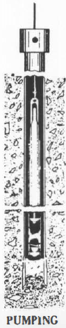
When the pump is at the bottom of the hole, the piston type plunger is at the bottom of the pump. By pulling on the sand drum lever, the plunger is rapidly raised, creating a strong vacuum, sucking in the gold, sand, mud, cuttings, etc. The efficiency of a sand pump depends on the speed with which the plunger is raised.
The foot valve in the bottom of the pump prevents material from escaping. Holding the sand drum lever out and keeping the sand drum engaged, brings the pump containing the core to the surface. Engineers very often drop several lead shot in the hole without the operator’s knowledge, and then count them after the pumping to see that everything was removed.
It is common practice to pump before and after driving. In loose ground it is often possible to pump out the core immediately after driving. When the two pumpings are made before and after driving, they are caught in the same bucket and concentrated in one operation. The pumpings are ordinarily emptied into a mud box.
When prospecting a deposit having a deep overburden of valueless material, a one-inch rod is driven into the ground and as the pump is brought up, the foot valve of the sand pump is set on the rod, thus opening the valve and washing the contents out on the ground. The driller must be careful, however, not to throw away the contents when gravel is reached. Extreme care should be exercised so that the last three or four inches of the core is left in the bottom of the drive pipe to form a plug.
After the stem has been lowered into the pipe, and the depth of the remaining core checked and recorded in the log book, the tools are raised. The drive clamps are bolted on and the operations repeated. After the first drive, the clamps are bolted on the top square. It is impossible to do this at the start, as bit would strike the core when driving.
PIPE PULLING
A SPECIAL FEATURE of the Hillman Drills is their remarkable pipe pulling ability.
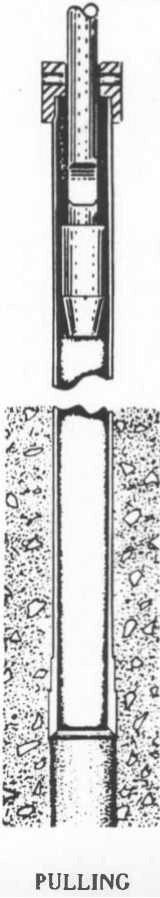
Using a top puller, the operation of pulling the pipe is as follows: The drive head is removed from the top of the casing. The knocking head is slipped over the pipe pulling jar. The rope socket is attached to the pin of the pipe pulling jar. Some operators prefer to use the rope socket and stem above the pipe pulling jar but a sharper blow seems to be obtained when it is below. The knocking head is screwed on the top of the pipe in place of the driving head. The drill is placed in the spudding position and the string of tools is raised far enough so that by means of the spudding action they are thrown at the driving head. A sharp blow is obtained rather than a straight pull. This is exactly the reverse action of pipe driving, the blow being directed at the lower face of the knocking head instead of the top of the driving head.
Sometimes considerable time is saved by using a hand hoist in conjunction with the bumping action. By thus having a tension on the line, the pipe does not have a chance to drop back after each blow and a continuous upward tension on the pipe is maintained.
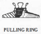
In extreme instances where the burden of jarring the pipe is too great for normal blow delivered and the upward tension of a hand hoist line is insufficient, a pipe pulling ring should be used. By placing the ring on the casing-head and hand jacks beneath the flange on the ring, a tremendous upward pressure is added to the jarring effect of the stem which starts the pipe upward.
PIPE PULLING WITH CASING SPEAR
Three jaws are used to eliminate distortion of the pipe as is usually the case when two jaws are used. Four jaws do not work as well as three jaws for six-inch casing and smaller, for not enough stock is then left in the center of the spear to withstand the constant hammering.
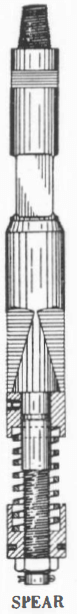
The operation of pulling the pipe by means of the spear is as follows: The string of tools is assembled, consisting of a rope socket, a stem, a set of long stroke jars and the trip casing spear. The jaws of the spear are set by using the spider furnished with the spear for pulling back the jaws and compressing the spring. The anvil block directly on top of the spring has a key which slides into a notch on the lower end of the spear; this key is pressed in. The spider is then removed. The string of tools is then lowered into the casing. Pulling is usually done from the last length. When the spear is in the last length of pipe it is hoisted up, sinking the jaws into the casing. The drill is placed in the spudding position and the string of casing jarred upwards. To release the casing, the spear is struck a sharp blow from the top. This causes the anvil block to strike the top of the jaws, which releases the spear. The tools are then hoisted out of the casing. The lengths of casing out of the ground are uncoupled and the operation repeated.
TREATMENT OF DRILL CORE
When the sand pump is hoisted out of the casing, the helper, or panner, grasps the lower end of the pump, walks back from the drill, and lays the lower end on the saddle of the dump (or mud) box. The hail end of the sand pump is then lowered into the bottom of the dump or mudbox. When the pump in this position the foot valve is approximately on an even height with the panner’s eye. While the pump is in this jackknifed position, it is thoroughly washed both inside and out. A dipper, formed by fastening a handle on a gallon tin can, is used for pouring water in the foot valve and flushing out the material. The pump is hoisted and jackknifed in the other position. The lower end of the pump on the previous washing is now the top. The second washing is not always essential, but is advisable, especially when working in rich ground. Directly below the lower end of the mud box is located a tub containing the volume bucket.
MUD BOX OR DUMP BOX
THE LEGS and sides of the dump box are made of surfaced fir, two inches by four inches. The trough is formed of 16-gauge steel. The top end of the box is welded solid. The lower end is also welded and fitted with an adjustable gate which can be set to control the flow into the volume bucket and avoid splashing.
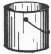
THE VOLUME BUCKET
The Volume Bucket, holding one cubic foot, is 13½ inches in diameter and 12 inches in height. The measuring stick is calibrated in tenths and hundredths of a cubic foot. A good practice is to measure the total quantity of material pumped from each hold and to compare the results from all holes drilled in similar material. A fair average can be obtained and used as a check on each separate property. Some operators calculate twenty cubic feet of material so measured to represent one cubic yard actually drilled.
The volume bucket measurement entails complete disintegration of the material and its reaggregation before measurement takes place. The escaping slimes may or may not fill the interstices of the sand with doubtful increase of the volume of the sand. Therefore, measurements made by this method will not always check with the theoretical volume or the volume as measured by the rise of the core in the pipe.
The material in the volume bucket is thoroughly stirred to break up any sticky lumps and then the water is poured off. Records are made in the log book of the measured volume of the core Directly beside the volume bucket is the panning table.
THE PANNING TABLE
The Panning Table is usually 28 inches high by 30 inches wide by 60 inches long. It has two wash tubs on top. A safety pan is placed in the bottom of each tub. A shelf is directly under the table top to hold the dish for holding the concentrates. The grizzly pan and the regular pan are also part of the equipment for the panning table. The grizzly pan has three-eight-inch holes. This allows the small material to wash through, and speedily eliminates the coarse material.
The material is taken out of the volume bucket with the gold scoop and placed in the grizzly pan which is in the second pan. The pans are usually filled two-thirds full. The stones and large cuttings are washed clean while the small particles fall through the grizzly pan into the second pan. The rocks are looked over and examined for nuggets before thrown out and the rough panning is done in the first tub. The fine panning is done in tub No. 2, where the water is clear. By having the water slightly warmed, the working conditions are more pleasant for the operator and also the clay tends to disintegrate more readily. The panner classifies the gold in one, two, and three colors. No. 3 is the finest, and consists of all particles weighing less than 1 Mg; No. 2 is gold consisting of all particles weighing between 1 Mg. and 4 Mg.; while No. 1 gold is any particle weighing over 4 Mg. The colors are recorded in the log hook. The concentrate is placed in a bottle, and marked with a Line Number, Hole Number, and Depth.
THE SAMPLE BOTTLES
For handling samples, some of the companies use small bottles similar to a vaseline jar. The cover is made of aluminum and of the screw type. The top of the cover is flat and has a dull finish, similar to a sand blasted surface. Writing with lead pencil is very legible on this type surface. The Line Number, Hole Number, Depth, and the panner’ signature are all written on top of the bottle.

After all values have been recorded and the bottles are again sent out in the field, the writing is removed by a scouring action with the thumb, using sand and water. This method eliminates the danger of lost labels. Remember: reliable evidence inspires confidence in the crews’ reports.
THE ROCKER
Directly beside the panning table is the rocker. The rocker, as used for checking drill samples, is very similar to the one used by the small individual placer operator. Some of the differences are: three-eighth-inch holes in place of half-inch-holes in the punched plate; punched portion of plate only two-thirds of half size used in the ordinary rockers, preventing all the material from being washed through with the first dipper of water. As the rocker is cleaned up so often, only two or three riffles are necessary.
TREATMENT OF GOLD
A few of the operators take the bottles of concentrate from the hole, carefully pan them down as far as possible, dry them, remove the magnetic material with a magnet, blow the remaining black sand off and then weigh the gold.
The usual procedure is to use a six-inch gold pan, pan the material down to a high concentrate, and them amalgamate the gold. This is done by rubbing the black sand and concentrate with mercury, then carefully panning off the black sand. This is usually caught in another pan and checked to see that no values have been lost. The samples are then usually placed in bottles marked for future reference. At this time it is well to qualitatively inspect the contents of the pan and black sands for platinum or unusual amounts of any of the other valuable metals or minerals which are apt to be found in placer deposits.
There are times when the gold does not readily amalgamate, due to oil or grease from the sand pump, pipe joints, vegetation, etcetera. Adding a little caustic potash usually eliminates this trouble. To amalgamate the gold, some operators add one or two drops of dilute nitric acid to the amalgam and concentrates and stir vigorously was a glass stirring rod until all the gold has been absorbed by the mercury.
The ball of amalgam is then carefully placed in a porcelain annealing cup or test tube. Dilute nitric acid (specific gravity 1.42, plus an equal volume of water) is added to the cup and the contents heated over the flame of an alcohol lamp. The mercury goes into solution with the nitric acid, leaving the natural alloy of gold and silver. The acid should be heated only enough to accelerate the reaction. Excessive or continual heating will dissolve the alloy in the gold and change its fineness. This loss of weight may cause an error, as the values are computed on the basis of natural fineness of the gold. The mercury nitrate is carefully washed from the gold and silver alloy, using a wash bottle with hot water. After adding a drop or two of alcohol to the annealing cup to prevent sputtering, it is heated over the alcohol lamp to a red heat or to a point as hot as the lamp will allow. The operation removes the moisture and burns away any carbon or lint which would salt the weight of the gold. The gold is then weighed and values recorded in the log book.
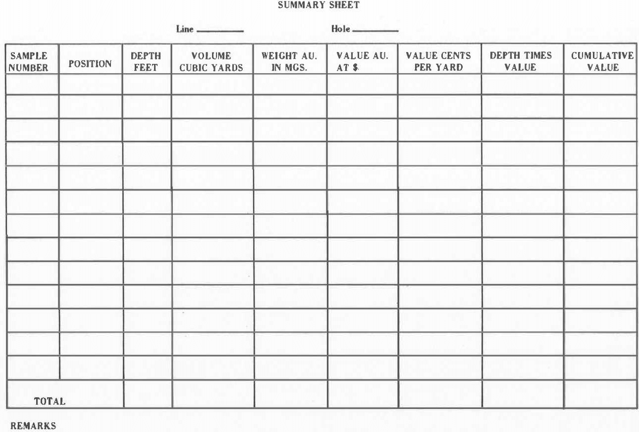
DRILL RIG LOG BOOK
An accurate systematic record should be kept of each hole drilled. Neat, accurate and carefully kept, and signed drillers logs are of the utmost importance and should be as carefully prepared as banking or legal papers. The reliability of a report on any placer deposit depends on the care with which the examination is conducted and recorded.
The driller and panner have a good opportunity to examine all the conditions relative to the deposit. All factors which may in any way have any bearing on the cost of the operation should be noted in the logs. Any corrections or compensation for lack of core should also be made in the field at the time, as later in the office, engineers might not fully understand all the conditions.
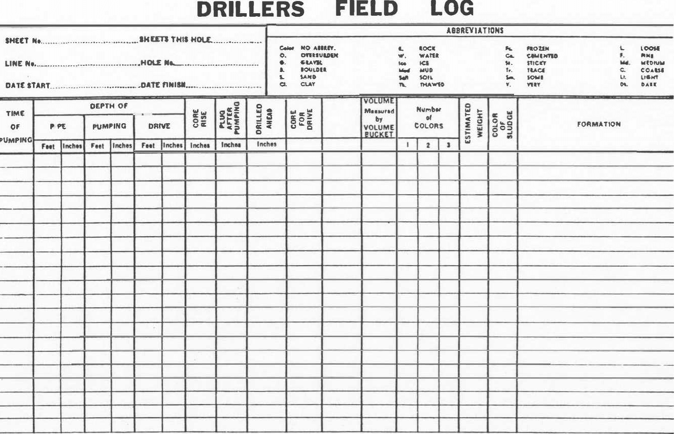
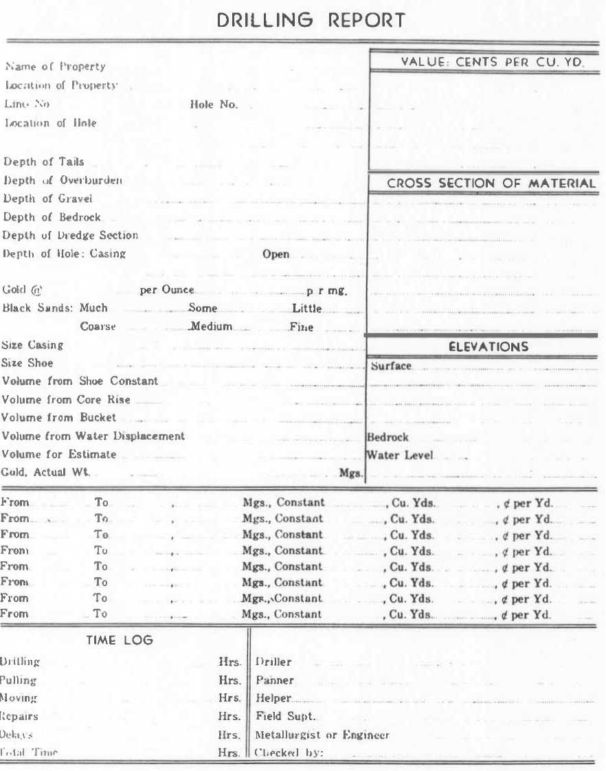
Explanations of Headings on Log Sheet
The following data is usually recorded on the log sheets:
1- Name of property
2- Location
3- Date
4- Line Number
5- Hole Number
6- Elevation
7- Time: Entries are made in this column of the time of day each pumping is made. At the bottom of the page the time consumed in drilling, pulling, moving, repairs, and delays is recorded. These records are helpful in detenning the cost of prospecting similar ground.
8- Depth of the cutting edge of the drive shoe: The last item in this column is the total depth drilled.
9- Depth of pumping: Care must be taken to see that pumping is not continued farther than within two inches of the lower edge of the drive shoe until bedrock has been reached or when a boulder is encountered. Notation should always be made when drilling below the shoe.
10- Entries are made of each individual drive.
11- The rise of the core in the pipe for each drive: This is the distance from the bottom of the drive shoe to the top of the core.
12- Core after pumping: The amount of core left in the pipe is naturally less than before pumping. This is the distance from the bottom of the drive shoe to the top of the core and is termed the plug. It usually varies from two to four inches.
13- The length of core removed: The difference between the core before pumping and the core after pumping shows the rise of the core in the pipe. Some operators use this in computing the volume. Volume computed by this method is known as the core volume by pipe measurement.
14- Volume Bucket measurement. This is exactly as the name implies, the volume as measured in the volume bucket.
15- Classification of colors: The number of colors are clarified in the No. 1, No. 2, and No. 3 sizes. No. 3 is the finest and consists of all particles weighing less than one milligram. No. 2 is the gold consisting of all particles weighing between one milligram and four milligrams. No. 1 gold is any particle weighing over four milligrams. These are recorded on the lines opposite the depths of drive, so that the various pay streaks will be known.
16- Estimated weight of gold: The panner becomes very proficient in estimating weight. He records the weight of the different colors in the log on lines corresponding with the depths at which they are found. This is helpful in following pay streasks.
17- Formation: The nature of the formation corresponding with the various depths is also noted. Very often the pay streak has a distinctive color. It is advisable to make a notation of this. The size and quantity of boulders have a definite hearing on how the property should be worked. Properties containing an unusual amount of clay require special washing equipment to prevent the clay from going through the boxes and picking up the gold. Some properties contain black sand which has a tendency to pack the riffles and decrease the amount of material which can be handled.
19- Depth and nature of over-burden: Very often the over-burden is removed by a different method than that used for working of the gravel. Information such as buried logs, large boulders, etc., have a direct bearing on the cost, and records should be made of them.
20- Labor conditions, transportation facilities.
21- Depth of the pay gravel.
22- Depth to bed rock.
23- Nature of bed rock.
24- Depth of pay in bed rock.
25- Diameter of the drive shoe.
26- Theoretical volume of the core removed.
27- Measured volume.
28- Weight of gold in milligrams. (mg.)
29- Fineness of the gold.
30- Constant used in making calculations.
31- Value in cents per cubic yard.
32- Price of gold at which values were computed.
33- Signatures of the driller, panner and helper.
A list of abbreviations is included at the top of the log sheet which simplifies the recording.
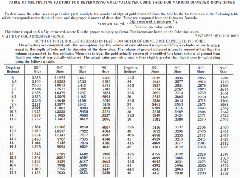
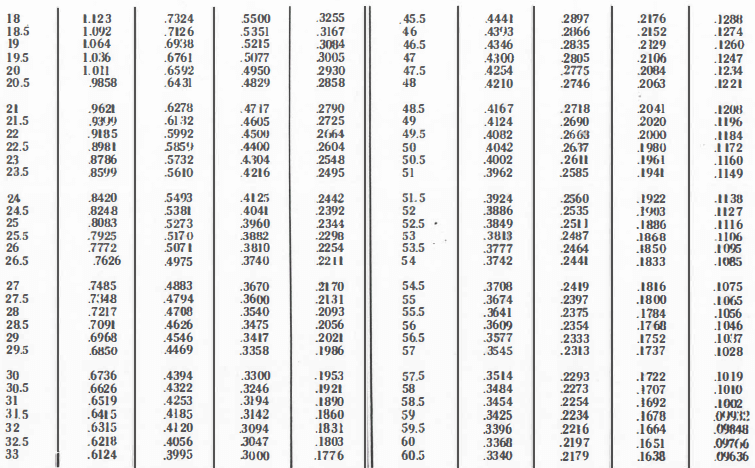
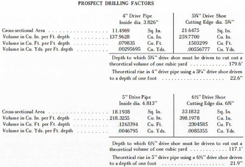
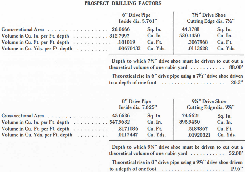
HILLMAN MULTIPLYING FACTORS
FOR DETERMINING GOLD VALUE PER CUBIC YARD
Using the theoretical value; Suppose that from a 40-foot hole using a 7½” drive shoe, 100 milligrams of gold are recovered. From the table of multiplying factors on the preceding page, find opposite the depth of 40 feet the factor .2475. Also suppose the relative fineness of the gold is 900. The value of the hole would be found as follows:
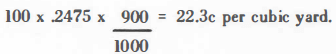
The above value would be correct providing a 100% core had been obtained.
Using a correction factor: The theoretical core rise per foot of drive will be found in the table of prospect drilling factors (see following page). In the above example it will be found that 40 feet x 20.3” = 812”, the theoretical core rise.
But suppose the actual measured core rise was 893 inches. The value in cents per cubic yard based on a 100% core would then be adjusted by multiplying it by 812/893, the ratio of actual to theoretical core rise. In our example the adjusted value would be
![]()
The same type of adjustment can be made using volume measurements in place of core rise. Some engineers calculate the adjustment both ways and apply the one giving the least plus correction. There are times when the correction is applied only to certain portions of a drill hole, that is, to sections containing significant values.